GRAVITY GOODS ROPEWAY
During the movement, the trolley moves back and
forth in the track rope so the minimal impact load
is imparted to the track rope. It is considered to
be 10 per cent of the total impact load.
As the impact is the change in momentum per
unit time, sudden application of brake should be
avoided to minimise the impact. For this, a braking
distance can be calculated and the operator
should be oriented on this to start application of
brake when the trolley reaches to the start of the
breaking distance so that uniform retardation is
achieved.
Maximum possible loads: Maximum possible load
in track rope = wt. of track rope + wt. of trolley +
wt. of downward moving goods + 50 per cent of
weight of haulage rope + 1/3rd of maximum wind
load + 10 percent of impact load
Maximum load in haulage rope = wt. of the
haulage rope + maximum wind load + 50 percent
of impact load.
The rope factor of safety should be checked for
the following two loading conditions:
Dead load + maximum wind load
Full load + 1/3rd of maximum wind load
+ impact load
As the gravity ropeways operate in the hilly
terrains, consideration of wind load is very crucial.
The operation of the ropeway during heavy storms
should be strictly prohibited.
3.1.5 Rope tension calculation
For rope tension calculation, first of all the rope
sag at dead load is assumed and the rope tension
is calculated for the corresponding sag. The full
load sag is then obtained from iterative methods
but more conveniently from computer analysis
like SAP.
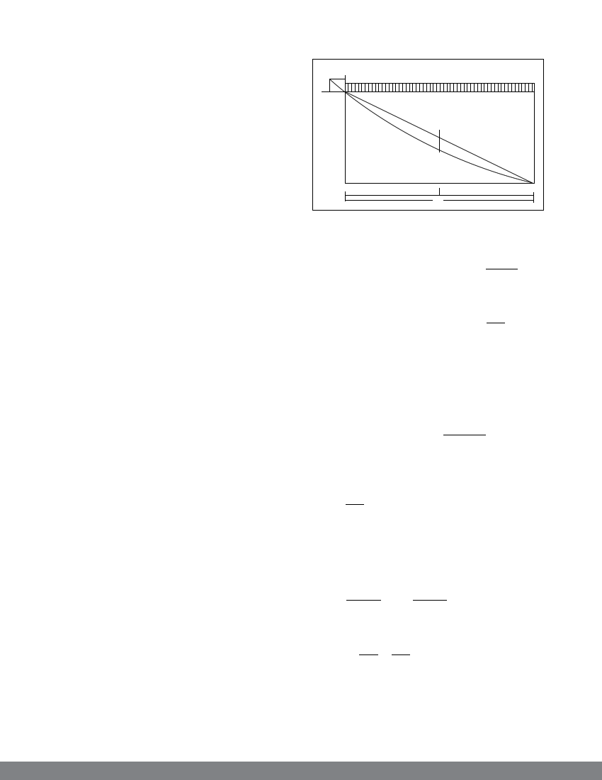
Tension in the wire rope is calculated from the
following relation.
T
H β1
w
w
bx
x
I
I-x
Figure 16
For uniformly distributed load (w)
Horizontal reaction at point x (Hx) = wx(l-x)
2bx
Hx is maximum when bx = b
Maximum horizontal reaction (H ) = wl2
8b
where w is weight per metre and b is the maximum
sag.
For point load (w)
When the point load is at x,
Horizontal reaction (Hx) = Wx (l -x)
bx
The reaction is maximum when the point load is
at the centre. Hence,
Hmax = WL
4b
where W is point load and b is the maximum
sag.
Point and live load in combination
At x,
Hx = wx(l-x) + Wx(l -x)
2bx bx
When bx = b,
Hmax = wl2 + Wl
8b 4b
20